The objective of the Real-Time Emissions Monitoring System (FS-EMS) from emission sources is to provide a custom and predesigned analytical tool which utilizes existing infrastructure, measures, and reports accurately the species-wise emission volumes by identifying sources in real-time via a corporate-wide web-based system. FS-EMS provides the companies a wider and clear vision of their sources connected to flaring/emission stacks and facilities, which will be particularly important for taking preventive and corrective actions based on system-generated reports, alerts, notifications, and KPIs.
FS-EMS allows performing a direct real-time data transfer between one or more DAHS which can further be interfaced with other DAHS, DCS, SCADA systems, data loggers, etc., connected to a company network.
FS-EMS incorporates a new and unique system that generates accurate, real-time presentation and detailed reporting of emission events from every source of a facility. The FS-EMS allows for monitoring of all emission sources at multiple processing facilities, with multiple plants, by utilizing existing plant real-time measurements of flows, pressures, temperatures, compositions, and other available process variables of control valves, monitoring devices, and any manual devices responsible for the facility emissions. By monitoring source-wise actual emission measurements, operators will be able to optimize the operation of their plants more effectively, resulting in minimization of emissions through the flare systems and/or discharged directly to the atmosphere as fugitive or stack emissions. FS-EMS will enhance the monitoring and reporting activities and mitigate the environmental impact of harmful Green House Gases (GHG) and other emissions like SOx, NOx, particulate matter, etc.
In the past, implementing an enterprise-wide emissions minimization plan was greatly hampered due to inadequate and/or faulty source-wise measurements of the emissions quantities. Known emissions measurement methods are difficult in their application, often expensive, and can be prone to failure. Further, in vast plant networks connected to many emissions sources, it was conventionally difficult to track and record data in real-time from the actual source to assign the causes of emissions. The analyzers and flow meters at the end of the pipe that record a facility’s total emissions are expensive to install, are maintenance intensive and do not reveal the actual sources in a complex plant.
What is Flaring, why and how it happens and why we need to minimize it?
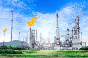
Gas and liquid flaring is an essential safety measure to burn the hydrocarbons and other harmful gases and liquids through a dedicated piping network and a combustion device called “flare” used in industrial plants such as petroleum refineries, chemical plants, natural gas processing plants as well as at oil or gas production sites having oil wells, gas wells, offshore oil and gas rigs and landfills. This method of disposal prevents dangerous over pressures in plant equipment by diverting gas and liquids for safe burning and also safely dispose the natural gas which cannot be piped to consumers during oil production.
The recent data released by the Global Gas Flaring Reduction Partnership (GGFR), a World Bank-led organization comprised of oil companies, governments, and international institutions shows 147 billion cubic meters (bcm) of natural gas was estimated flared in 2015 up from 145 bcm in 2014 and 141 bcm in 2013.
The above data does not include the flaring from refineries, petrochemical plants, landfills etc which could be significant. Many environmentally responsible companies over the years have tried to minimize the flaring however still daily flaring consists of purge gas, daily leakages, design, and operational swings and design limitations. This is because the flare gas recovery systems are expensive and difficult to operate and there are no mandatory regulations in many countries.
The impact of flaring is of local and global concern. Gas flaring is one of the most challenging energy and environmental problems the world is facing today both regionally and globally. For example, flaring/venting during oil production operations emits CO2, methane and other forms of gases which contribute to global warming causing climate change, and this affects the environmental quality and health of the vicinity of the flares. Hence it makes sense to avoid the unnecessary release of carbon dioxide or methane into the atmosphere, where practicable.
Why you need a REAL TIME FLARE MONITORING SYSTEM
In the current context, environmentally responsible production is a corporate goal of every company. Further, in global context stricter environmental regulations for flaring and greenhouse gases through UNFCCC are imposed. Hence the current legislative trends emerging from Global Methane Initiatives, COP21 in Paris indicates new regulations on emission reductions will be imposed in future and real time monitoring systems will be mandated soon.
What is a REAL TIME FLARE MONITORING SYSTEM
It is the intent of Flare Monitoring System to provide custom and predesigned analytical tools utilizing existing infrastructure, which measures and reports accurately the gas emissions and identifies sources in real time via a corporate wide web based system. By corporate wise web based system, companies will have wider and clear vision of their Flaring Stacks and Devices in facilities, which will be very important for taking preventing and corrective actions based on system generated reports and KPIs.
Industry proven system
Flare Monitoring System was designed and developed by Saudi Aramco to capitalize on real time monitoring systems and thereby reduction of flaring at more than 1200 sites of Oil producing, gas processing and refining facilities
In addition to implementation and design of analysis and reporting system with configurable KPIs, Flare Monitoring System will create a platform to assist plant management in making good decisions to identify and analyze root causes for flaring, reducing gas emission as well meeting standard rule, regulation and goals.
Saudi Aramco has reduced the flaring and GHG emissions by more than 50% resulting in monetary savings of more than 250 million of dollars since the implementation of Flare Monitoring System. Moreover, it provides a consistent centralized data collection, reporting, analyzing and validating tool through corporate wide web system.
Greenhouse Gas (GHG) data management and information systems are critical for developing and regularly updating industrial and national greenhouse gas (GHG)inventories that, in turn, are foundational to national and international GHG mitigation efforts.
However, limited information exists regarding national GHG inventory data management and information systems. GHG emission inventories are generally prepared through manual procedures by different departments and agencies, as a result, there is high chance of missing some GHG emission data as well double entry of some GHG emission data. Thus, it may cause generation of inaccurate GHG emission inventories.
Accurate and reliable GHG emission inventories data is pivot for policy maker to come up environment policies for controlling GHG emission. If there is inadequate or inaccurate GHG emission data available to the agencies, then it would be difficult for them to have appropriate and effective policies.
Industrial Prosperity specializes in developing real time GHG emission data management from facilities using cutting edge emission sensing technology and advanced software systems. With the implementation of these systems, accurate and effective GHG emission data management and inventories can be prepared in real time providing vital information to the facilities. A country wide data system can also be developed with consistent and accurate data which helps decision-makers understand emission trends and formulate mitigation activities, among other functions.
Thus it will provide up to date GHG emission national wide inventory at the fingertip. Real time GHG emission data and inventories can be shared with government and relevant agencies thus providing them with vital information to take a proactive decision in crafting effective policies and fine tuning the current policies to get determined outcome.
The regulated air pollutants are those pollutants such as Sulfur Dioxide (SO2), Nitrogen Dioxide (NO2), Ozone (O3), Hydrogen Sulfide(H2S), Particulate Matter, Carbon Monoxide (CO), Lead(Pb), Benzene (C6H6) and other hazardous pollutants for which government standards and regulations have been established. Flaring is also a major issue of environmental concern due to its associated emissions.
Oil and natural gas drilling rigs are used to identify geologic reservoirs and also to create holes that allow the extraction of oil or natural gas from those reservoirs. Primarily in onshore oil and gas fields once a well has been drilled, the drilling rig will be moved off of the well and a service rig (a smaller rig) that is purpose-built for completions will be moved on to the well to get the well online.
Oil refineries, processing plants, pipelines, storage farms, LPG/LNG plants, and offshore platforms all utilize or produce a wide range of hazardous combustible and toxic gases. Furthermore, the processes involved in each can produce nontoxic gases which when amassed in high concentrations, depletes oxygen causing a hazardous condition to personnel who occupy the area without proper protection.
Oil and gas facilities can be expected to accidentally and routinely emit hydrogen sulfide in concentrations that span a wide range and are associated with a variety of health effects.
Hydrogen sulfide is a naturally occurring component of crude oil and natural gas. Petroleum oil and natural gas are the products of thermal conversion of decayed organic matter (called kerogen) that is trapped in sedimentary rocks. High-sulfur kerogens release hydrogen sulfide during decomposition, and this H2S stays trapped in the oil and gas deposits.
Hydrogen Sulfide (H2S) is a major hazard encountered at drilling sites. Leaks in drilling applications can release large quantities of H2S thus in turn can spread to nearby communicating can effect released, which becomes extremely hazardous to well-site personnel. Areas that are susceptible to leaks include the drillers stand, blow-out preventer, shale shaker and mud tank.
Methane (CH4) is the predominant component of natural gas, comprising 70 to 90 percent, while other gaseous hydrocarbons, butane (C4H10), propane (C3H8), and ethane (C2H6), account for up to 20 percent. Contaminants present in natural gas, which have to be removed at natural gas processing facilities, include water vapor, sand, oxygen, carbon dioxide, nitrogen, rare gases such as helium and neon, and hydrogen sulfide. In fact, hydrogen sulfide is the predominant impurity in natural gas. The Environmental Protection Agency (EPA) classifies natural gas as sour when H2S is present “in amounts greater than 5.7 milligrams per normal cubic meters ( mg/Nm3) ( 0.25 grains per 100 standard cubic feet )
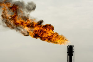
Flare stacks are used in many industries to burn off unwanted waste gas byproducts, or flammable gasses released by pressure relief valves during unplanned over‐pressuring of plant equipment.
Flare systems are often a last line of defense that prevents dangerous hydrocarbon pollutants from entering the atmosphere. One example is methane, which is not only combustible, but is also 23 times more potent than CO2 as a greenhouse gas.
Thermal imaging cameras are an ideal monitoring tool, since they allow automated remote monitoring on a 24/7 basis in virtually any weather.
Thermal imaging cameras benefits:
- Verify combustion, minimize unburned pollutants
- Instantly report loss of combustion with visual and audible alarms
- Provide remote visual monitoring with a TV or PC display
- Provide a quantitative temperature readout
- Can notify plant management via email and intranet connections
- Can be connected to a central control room via Ethernet
- Work day and night, seven days a week and in any weather
Thermal imaging cameras offer a solution:
Thermal imaging cameras recognize the difference in the heat signature of a flare stack flame and the surrounding background (usually, the sky or clouds). In addition to detecting stack flame, these cameras can be positioned to monitor the igniter flame. Typically, cameras are mounted on a pedestal or other rigid structure in moisture resistant housings to protect them from harsh weather conditions.
The camera’s spectral response and calibration allows it to see through moisture in the air to obtain a good image and relative temperature reading of the flare stack or pilot flame. The images obtained with thermal imaging cameras even allow an observer to detect stack flame that might not be visible to the naked eye because of its composition or low gas flow volume. This overcomes problems associated with UV flame detectors, which can be blinded by smoke. Thermal and visual images can be transmitted in real time to a central control room as either analog or digitized data.